WHAT IS FLANGE?
- A flange is a method of connecting pipes, valves, pumps and other equipment to form a piping system. It also provides easy access for cleaning, inspection or modification. Flanges are usually welded or screwed. Flanged joints are made by bolting together two flanges with a gasket between them to provide a seal.
TYPES OF FLANGES:
- Welding Neck Flange
- Slip On Flange
- Socket Weld Flange
- Lap Joint Flange
- Threaded Flange
- Blind Flange
1. WELDING NECK FLANGE:
- Welding Neck Flanges are easy to recognize at the long tapered hub, that goes gradually over to the wall thickness from a pipe or fitting.
- The long tapered hub provides an important reinforcement for use in several applications involving high pressure, sub-zero and / or elevated temperatures.
- These flanges are bored to match the inside diameter of the mating pipe or fitting so there will be no restriction of product flow. This prevents turbulence at the joint and reduces erosion.
- This flange type will be welded to a pipe or fitting with a single full penetration, V weld (Butt weld).
2. SLIP ON FLANGE:
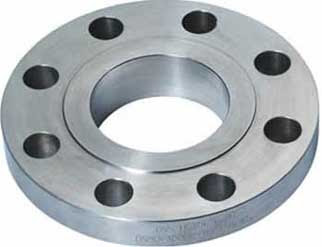
- The calculated strength from a Slip On flange under internal pressure is of the order of two-thirds that of welding neck flanges, and their life under fatigue is about one-third that of the latter.
- The connection with the pipe is done with 2 fillet welds, as well at the outside as also at the inside of the flange.
- A disadvantage of the flange is, that principle always firstly a pipe must be welded and then just a fitting. A combination of flange and elbow or flange and tee is not possible, because named fittings have not a straight end, that complete slid in the Slip On flange.
3). SOCKET WELD FLANGE:
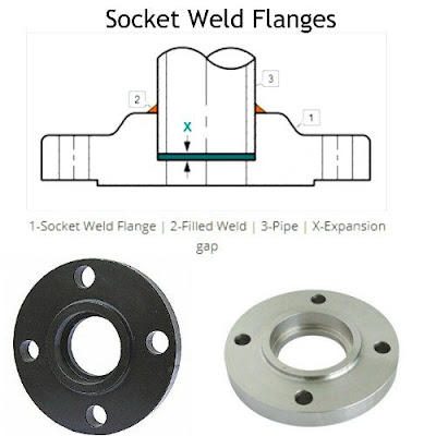
- Socket Weld flanges were initially developed for use on small - size high pressure piping. Their static strength is equal to Slip On flanges, but their fatigue strength 50% greater than double-welded Slip On flanges.
- The connection with the pipe is done with 1 fillet weld, at the outside of the flange. But before welding, a space must be created between flange or fitting and pipe.
- The purpose for the bottoming clearance in a socket weld is usually to reduce the residual stress at the root of the weld that could occur during solidification of the weld metal. The image shows you the X measure for the expansion gap.
4). LAP JOINT FLANGE:
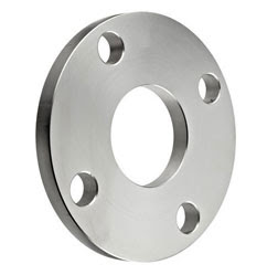
- Lap Joint Flanges have all the same common dimensions as any other flange named on this page however it does not have a raised face, they used in conjunction with a "Lap Joint Stub End".
- These flanges are nearly identical to a Slip On flange with the exception of a radius at the intersection of the flange face and the bore to accommodate the flanged portion of the stub end.
- Their pressure-holding ability is little, if any, better than that of Slip On flanges and the fatigue life for the assembly is only one tenth that of welding neck flanges.
- They may be used at all pressures and are available in a full size range. These flanges slip over the pipe, and are not welded or otherwise fastened to it. Bolting pressure is transmitted to the gasket by the pressure of the flange against the back of the pipe lap.
5). Stub End:
- A Stub End always will be used with a Lap Joint flange, as a backing flange.
- This flange connections are applied, in low-pressure and non critical applications, and is a cheap method of flanging. In a stainless steel pipe system, for example, a carbon steel flange can be applied, because they are not come in contact with the product in the pipe.
6). THREADED FLANGE:
- Threaded Flanges are used for special circumstances with their main advantage being that they can be attached to the pipe without welding. Sometimes a seal weld is also used in conjunction with the threaded connection.
- Although still available in most sizes and pressure ratings, screwed fittings today are used almost exclusively in smaller pipe sizes.
7). BLIND FLANGE :
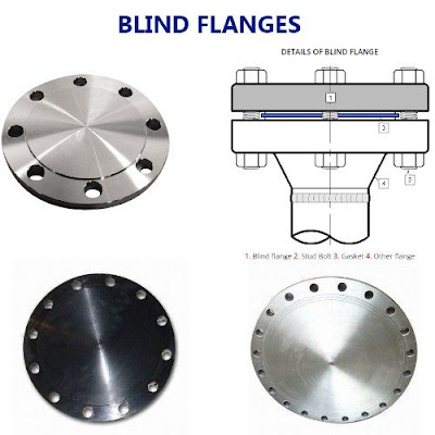
- Blind Flanges are manufactured without a bore and used to blank off the ends of piping, valves and pressure vessel openings.
- From the standpoint of internal pressure and bolt loading, blind flanges, particularly in the larger sizes, are the most highly stressed flange types
FLANGE FACES:
- Different types of flange faces are used as the contact surfaces to seat the sealing gasket material.
- ASME B16.5 and B16.47 define various types of flange facings, including the raised face, the large male and female facings which have identical dimensions to provide a relatively large contact area.
- Other flange facings covered by these standards include the large and small tongue-and-groove facings, and the ring joint facing specifically for ring joint type metal gaskets.
RAISED FACE (RF):
- The raised face flange face is the most common type used in process plant applications, and is easily to identify. It is referred to as a raised face because the gasket surfaces are raised above the bolting circle face
- This face type allows the use of a wide combination of gasket designs, including flat ring sheet types and metallic composites such as spiral wound and double jacketed types.
- The purpose of a RF flange is to concentrate more pressure on a smaller gasket area and thereby increase the pressure containment capability of the joint
FLAT FACE (FF):
- The flat face flange has a gasket surface in the same plane as the bolting circle face. Applications using flat face flanges are frequently those in which the mating flange or flanged fitting is made from a casting.
- Flat face flanges are never to be bolted to a raised face flange.
RING-TYPE JOINT (RTJ):
- This type is typically used in the most severe duties, for example, in high-pressure-gas pipe work.
- Ring-type metal gaskets must be used on this type of flange facing
- The ring type joint flanges are typically used in high pressure and/or high temperature services above 800°F (427°C).


.jpg)

0 Comments